Step 24
![]() On
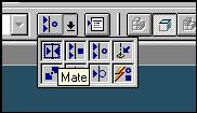
the Place Part SmartStep ribbon bar, in the Relationship
On
the Place Part SmartStep ribbon bar, in the Relationship
Type list, click the Mate button.
Step 25
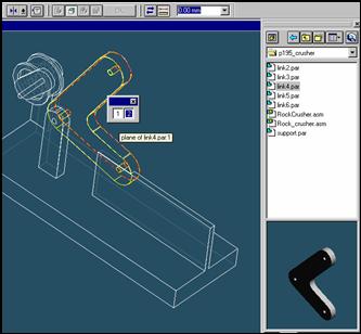
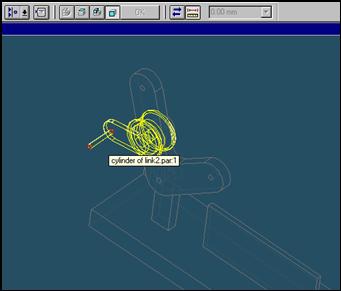
![]() Position
the mouse cursor over the the edge of link4 and wait it change to
Position
the mouse cursor over the the edge of link4 and wait it change to
![]() , and
click.
, and
click.
 and the
QuickPick tool is displayed. Move the cursor over the different boxes
and the
QuickPick tool is displayed. Move the cursor over the different boxes
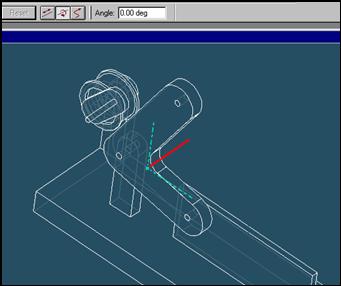
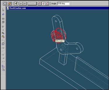
on QuickPick. Use QuickPick to highlight the planar face on the link4 shown in the illustration,
and click to select it.
Step 26
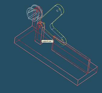
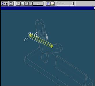
Select the support part to mate in the assembly
In the assembly window, select the support.
Step 27
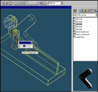
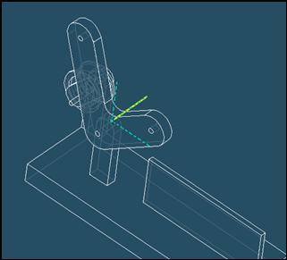
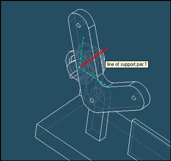
Selecting the mating face of the support part
Use QuickPick to select the left face of support part, as shown in the illustration.
Step 28
![]()
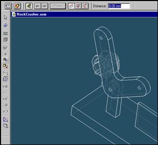
![]() On
the Place Part SmartStep ribbon bar, click OK
On
the Place Part SmartStep ribbon bar, click OK
Step 29
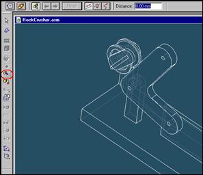
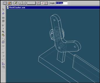
Click on Move Part Button and then click on Rotate Button
Step 30
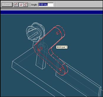
Click on the link4 part.
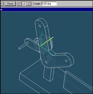
Step 31
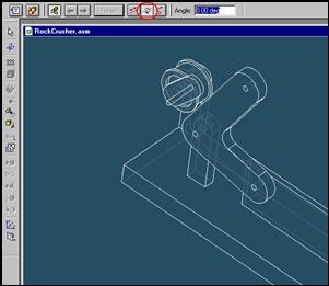
Click on the axis to rotate and move cursor with holding left mouse button
Step 32
Click on Move Part Button and then click on Rotate Button
Step 33
Click on the link2 part.
Step 34
Click on the axis to rotate and move cursor with holding left mouse button
Step 35
![]()
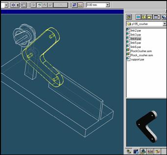
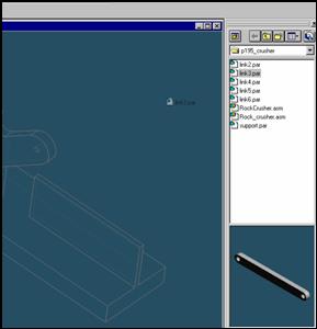
On the EdgeBar tool, click the Parts Library tab.
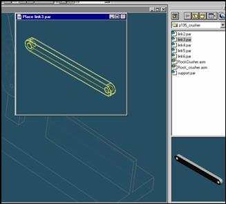
In the file list area on the Parts Library tab, select the file named
Link3.par, hold down the left mouse button, drag the file into the
assembly window, and then release the mouse button.
Step 36
![]()
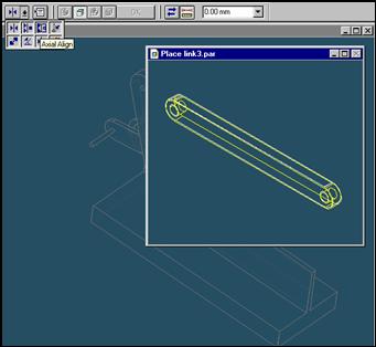
On the Place Part SmartStep ribbon bar, in the relation type list,
click the relationship Types list, click the Axial Align button.
Step 37
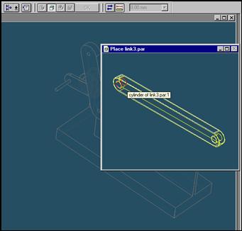
Select the Axis to Align
In the Place part window, select the hole which is at the end of link3 part.
Step 38
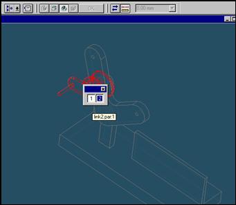
In the assembly window, select the link2 part.
Step 39
Select the aligning axis on the link2 part
In the Assembly window, select the shaft of the link2 part.
Step 40
![]()
![]()
On the Place SmartStep ribbon bar, click OK
| Previous | Next |