
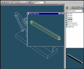
Step 62
![]()
On the EdgeBar tool, click the Parts Library tab.
In the file list area on the Parts Library tab, select the file named
Link5.par, hold down the left mouse button, drag the file into the
assembly window, and then release the mouse button.
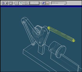
Step 63

![]()
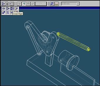
On the Place Part SmartStep ribbon bar, in the relation type list,
click the relationship Types list, click the Axial Align button.
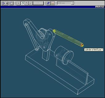
Step 64

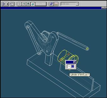
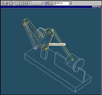
Select the Axis to Align
In the Place part window, select the hole which is at the end of link5 part.
Step 65

In the assembly window, select the link4 part.
Step 66

Select the aligning axis on the link4 part
In the Assembly window, select the hole of the link4 part.
Step 67
![]()
![]()
On the Place SmartStep ribbon bar, click OK
Step 68
![]()
On the Place Part SmartStep ribbon bar, in the relation type list,
click the relationship Types list, click the Axial Align button.
Step 69
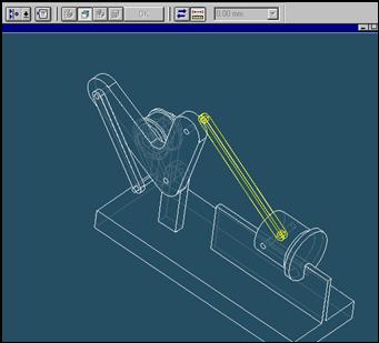
Select the Axis to Align
In the Place part window, select the hole which is at the end of link4 part.
Step 70

In the assembly window, select the link6 part.
Step 71
Select the aligning axis on the link6 part
In the Assembly window, select the hole of the link4 part.
Step 72
![]()
![]()
On the Place SmartStep ribbon bar, click OK
Step 73
![]() On
the Place Part SmartStep ribbon bar, in the relation type list,
On
the Place Part SmartStep ribbon bar, in the relation type list,
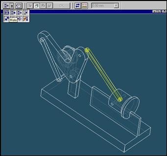
click the relationship Types list, click the Mate button.
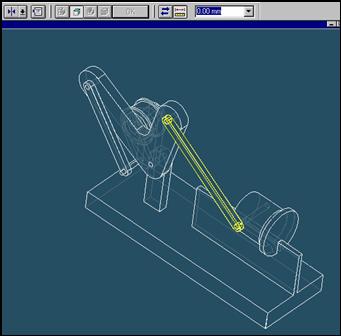
Step 74
Select the face to mate
In the Place part window, select the right face of link5 part as illustration.
Step 75

In the assembly window, select the link4 part.
Step 76
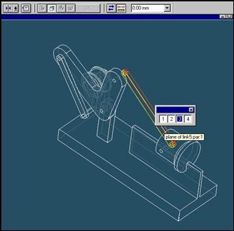
Select the mating face of the support part
In the Assembly window, select the left face of link4 part.
Step 77
![]()
![]()
On the Place SmartStep ribbon bar, click OK
| Previous | Next |