Step1
Start Solid Edge : Assembly

If Solid Edge is not already running, on the
Start menu, point to Programs, point to Solid Edge
and then click Solid Edge Assembly.
Step2
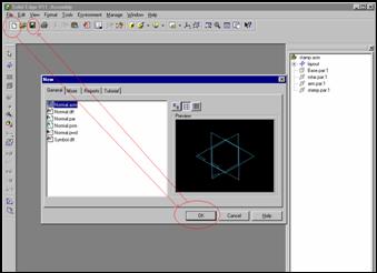
Open a New File and Save
![]()
![]()
![]()
![]()
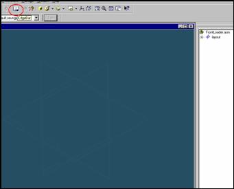
Step 3
![]() If
the EdgeBar tool is not displayed, on the Main Toolbar, click
If
the EdgeBar tool is not displayed, on the Main Toolbar, click
The EdgeBar button
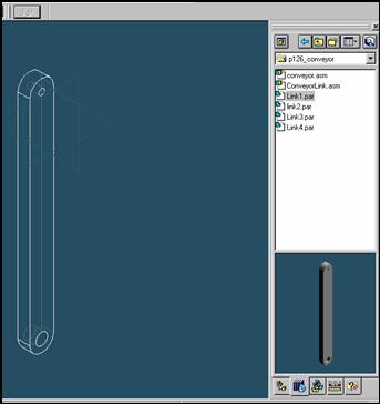
On the EdgeBar tool, click the parts Library tab
![]()
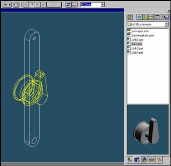
Step 4
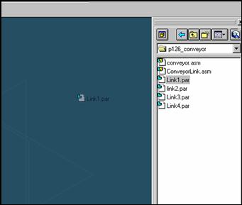
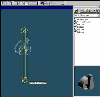
Select the link1.asm from the Parts Library list in EdgeBar
and then drag into the assembly.
Step 5
![]() On
the EdgeBar tool, click the Assembly PathFinder tab
On
the EdgeBar tool, click the Assembly PathFinder tab
Step 6
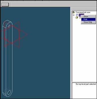
Click the right mouse button on the layout to display
the shortcut menu.
On the shortcut menu, click the hide command with
the left mouse button.
Step 7
![]()
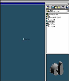
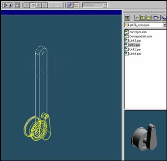
On the EdgeBar tool, click the Parts Library tab.
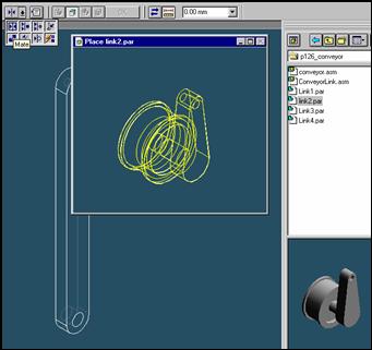
In the file list area on the Parts Library tab, select the file named
Link2 hold down the left mouse button, drag the file into the
assembly window, and then release the mouse button.
Step 8
![]() On
the Place Part SmartStep ribbon bar, in the relation type list,
On
the Place Part SmartStep ribbon bar, in the relation type list,
click the relationship Types list, click the Mate button.
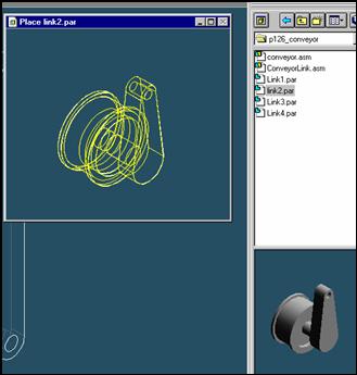
Step 9
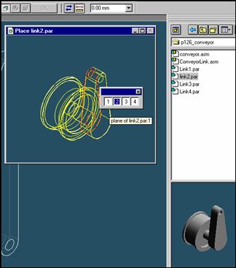
Select the face to mate
In the Place part window, select the left face of link2 part.
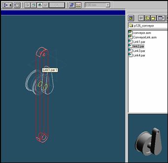
Step 10
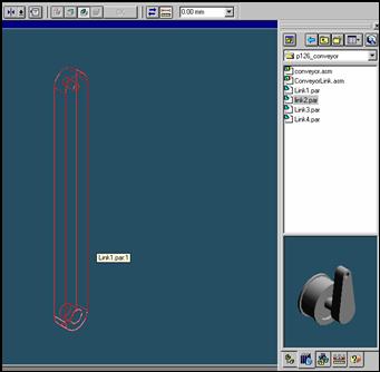
In the assembly window, select the link1 part.
Step 11
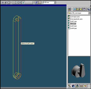
Select the mating face of the link1 part
In the Assembly window, select the right face of the link1
Step 12
![]()
![]()
On the Place SmartStep ribbon bar, click OK
Step 13
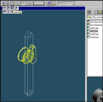
![]()
On the Place Part SmartStep ribbon bar, in the relation type list,
click the relationship Types list, click the Axial Align button.
Step 14
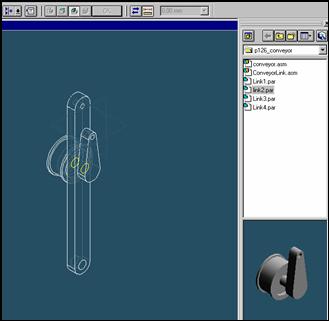
Select the Axis to Align
Select the axis at the center of the link2 part.
Step 15
In the assembly window, select the link1 part.
Step 16
Select the aligning axis on the link1 part
In the Assembly window, select the under hole on the link1 part.
Step 17
![]()
![]()
On the Place SmartStep ribbon bar, click OK
| Previous | Next |