Introduction
![]()
![]()
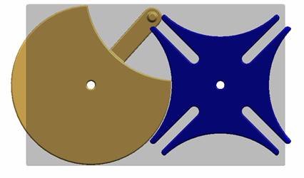
This tutorial uses a Geneva Wheel as an example to teach the kinematic and dynamic analysis using Solid Edge and Dynamic Designer.
|
|
|
|
Geneva wheel |
Cam-Follower Mechanism |
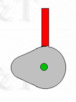
The mechanism used in this example is specific form of Cam-Follower Mechanism. A Cam-Follower Mechanism consists of 3 links the frame (or ground), the cam, and the follower. It is connected by two pin joints and the Cam-Follower contact.
As designated in the figure, there are three links. Link 1 is the driver. Link 2 is the Geneva wheel. Link 3 is ground.
The following table summarizes the joints.
|
Joint Number |
Formed between links |
Joint type |
|
1 |
Link 1 and Link 3 |
Revolute (or Pin) |
|
2 |
Link 2 and Link 3 |
Revolute (or Pin) |
|
3 |
Link 1 and Link 2 |
Cam-Follower contact |
Degrees of Freedom: According to Gruebler’s equation,
![]()
where F = Degrees of Freedom (DOF)
n = total number of links in a mechanism
![]() = total number of primary joints (pins or sliders)
= total number of primary joints (pins or sliders)
![]() = total number of higher-order joints (cams or gears)
= total number of higher-order joints (cams or gears)
we have,
F = 3(3-1) – 2(2) – 0
= 5 – 4 - 0
= 1.
Hence, Cam-Follower mechanism has 1 DOF. In other words, Cam-Follower mechanisms are constrained or fully operated with one driver.
Click here to get the compressed (Solid Edge) part files.