Lab 3 – Basic Stamp
II – Speed Control of a DC Motor
Assigned: March 21st 2003 Due: April 10th 2003
One principal area that
has seen a tremendous increase in use of microcontrollers and digital control
is industrial process control. The primary reason for this popularity is the
tremendous flexibility offered by such a system to implement a variety of
control laws coupled with the flexibility of changing these control laws on the
fly. Hence, in this lab we will investigate one such implementation using the
“Speed control of a DC Motor” as the central example.
For this lab project, we will use several parts from the Parallax Industrial Control Parts Kit – which is provided. Wherever possible, we will try to provide cross-references to specific chapters/exercises/pages in the Industrial Control Student Guide Manual that accompanies this kit (and can be downloaded from the Website). However, we would also encourage you to take the time to read through the manual thoroughly prior to implementing this system – many of the ideas are explored in great detail in the manual (although in a different context – that of temperature control in an industrial process).
Objectives:
Our overall goal is
speed control of a DC motor. In doing so, we also wish to expose you to aspects
of:
(i)
creation
and calibration of new “digital sensors” – specifically building and
interfacing a digital encoder to quantize and measure angular motions (with
focus on angular velocity measurement).
(ii) interfacing
actuators along with necessary drive electronics – specifically examining the
interfacing a DC fan motor to the BS2;
(iii) using
different control laws to try to achieve desired performance criteria –
specifically examining one or more of the following control schemes (on-off,
differential gap, P, PD, PID); and
(iv) quantitatively
logging the resulting data to evaluate the actual performance -- specifically
examining creation of a real-time logging interface using a Real-Time Clock
with Stamp Plot Lite.
Please take care
regarding the following issues: Polarity of the Motor, maximum and minimum
voltage ratings for the motor. Please also note that the manual refers to a different
board (a Board of Education) where the maximum d.c. voltage available on the
board is 9V. On your Stamp Works kit, you have a 12 V, 500 mA supply from the
wall supply that is explicitly available to you at a header.
Some suggested stages in the development
process:
The manual for the
Industrial Control Kit is provided in
http://www.parallax.com/Downloads/Documentation/edu/Industrial_Control.pdf
And local copy can be
found here.
Stage 1: Build
and calibrate the encoder (for speed only)
The process of creating and
calibrating a retro-reflective switch is discussed on pages 47-50.
The process of
creating and calibrating a tachometer using the dc fan motor is discussed in
great detail on pages 52-55.
Stage 2: Calibrate the open-loop control of the fan
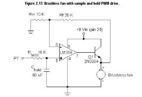
Detailed information for controlling the motor using a PWM command, coupled to a sample/hold circuit and Op-Amp/Transistor pair to drive the fan is given on pages 59-63. Specifically, given the circuit shown in Figure 2.17 – redesign it so that you could take advantage of the new 12V supply and the effective voltages across the fan are between 0 and 10V (i.e. PWM output with a duty cycle 0 gives 0V and 255 gives 10V – leaving a small margin so as to avoid swings of output voltage to 12V).
Stage 3:
Implement the closed-loop control of the fan.
You can investigate many of the
different control schemes – on-off, differential gap, P, PD, PID that are
discussed in greater detail in Experiments 4, 5 and 6 of the Industrial Control
Kit manual (in a different process control context – that of temperature
control). All of you should be reasonably familiar with the basics of these
different types of control -- be innovative in trying to create conditions that
let you examine the effects of the control actions. For example, you could try
introducing systematic loads/disturbances on the system by using a flapping
piece of paper that obstructs the motion of the vanes of the fan.
Stage 4:
Logging quantitative “engineering data” and use for post-processing.
Beginning with Experiment 1, there is an ongoing discussion on use of Stamp Plot Lite interfaced to your BS2 using an asynchronous serial connection, you will find that this is particularly useful in visualizing and evaluating the overall performance of your system. Experiment 7 examines some of the issues regarding the real-time logging of data.
Some details about Stamp Plot Lite:
http://www.parallax.com/html_pages/downloads/software/stamp_plot_pro_info.asp
or local copy can be found here.
And to download:
http://www.parallax.com/Downloads/Software/StampPlot_Lite.zip (Right click and save)
or local copy can be found here.
Reporting:
Provide a
self-standing document, which could be used as an “Application Note” which
describes and explains your system and would enable someone else to replicate your
work. Document your system with a circuit diagram, list of components, and
parts cost estimate. Include a listing of your program with thorough
comments:
·
Please follow the guidelines provided
at http://www.eng.buffalo.edu/Courses/mae576/ReportFormat.htm.
·
For sample reports see http://www.eng.buffalo.edu/Courses/mae576/SampleReport.pdf
and http://www.eng.buffalo.edu/Courses/mae576/Spring2002/LAB_REPORTS/.
Each group should
send in a weekly e-mail to the TA, Mr. Chin-Pei Tang (chintang(at)buffalo.edu) briefly outlining
their progress for the week and outlining a schedule for proposed completion of
the rest of your lab assignment by the group (these will be due on the Thursday
of each week).