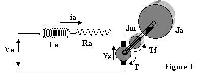
Figure 1 below represents a schematic of a DC motor. This device converts
electrical energy (when operating as a "motor") or it can convert mechanical
energy into electrical energy when operating as a "generator".
In motor operation it is controlled by input to its armature (through brushes
and a commutator). It also has a magnetic field, which is either supplied by a
separate voltage supply or is furnished by a strong permanent magnet. When the
armature is conducting current in the magnetic field, it produces a mechanical
torque on the shaft proportional to the current ![]() . As it rotates in the magnetic field
it also generates a voltage proportional to the speed of rotation
. As it rotates in the magnetic field
it also generates a voltage proportional to the speed of rotation ![]() .
.

To model the motor, both the mechanical side including any added load and the
electrical circuit side must be modeled. On the circuit side, the inductor is
the energy storage element so that

where the generated voltage must be subtracted from the applied armature
voltage. On the mechanical side F=ma is applied in rotational form so that

These equations are then the basis of the state equations which describe the
motor behavior in compact form. Before combining, we recognize that the total
inertia of motor and added load is ![]() and that the generated
voltage
and that the generated
voltage ![]() with the
torque produced by the motor proportional to current as
with the
torque produced by the motor proportional to current as ![]() . The frictional torque
. The frictional torque ![]() is generally related to
motor speed but represents any type of friction tending to slow down the motor.
The state equations finally become
is generally related to
motor speed but represents any type of friction tending to slow down the motor.
The state equations finally become


Once appropriate parameter values have been obtained for the constants above,
the equations can be used to simulate motor transient behavior with MatLab. With
a linear representation for friction torque in the form ![]() , the routines lsim or
step can be used. With a nonlinear friction representation (or linear as
well), the ode23 or similar nonlinear solver can be used.
, the routines lsim or
step can be used. With a nonlinear friction representation (or linear as
well), the ode23 or similar nonlinear solver can be used.