|
|
|
|
Water Nozzle |
Four-Bar Mechanism |
Introduction
This tutorial uses Water Nozzle as an example to teach the kinematic and dynamic analysis using Solid Edge and Dynamic Designer.
|
|
|
|
Water Nozzle |
Four-Bar Mechanism |
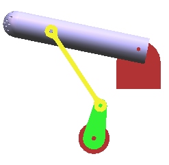
The mechanism used in this example is simple Four-Bar Mechanism. Four-Bar Mechanism consists of four links with one being designated as frame (or ground). It is connected by four pin joints.
As designated in the figure, there are four links link 1, link 2, link 3 and link 4. Link 1 acts as a crank. Link 2 acts as connecting link, link 3 is the nozzle and link 4 is ground.
The following table summarizes the joints.
|
Joint
Number |
Formed
between links |
Joint
type |
|
1 |
Link 4 and Link 1 |
Revolute
(or Pin) |
|
2 |
Link 1 and Link 2 |
Revolute
(or Pin) |
|
3 |
Link 2 and Link 3 |
Revolute
(or Pin) |
|
4 |
Link 3 and Link 4 |
Revolute
(or Pin) |
![]()
n = total number of links in a mechanism
![]() = total number of primary joints
(pins or sliders)
= total number of primary joints
(pins or sliders)
![]() = total number of higher-order
joints (cams or gears)
= total number of higher-order
joints (cams or gears)
we have,
F = 3(4-1) – 2(3+1) – 0
= 9 – 8 - 0
= 1.
Hence, Four-Bar mechanism has 1 DOF. In other words, Four-Bar mechanism is constrained or fully operated with one driver.
Click here to get the compressed (Solid Edge) part files.