|
|
|
|
Valve Actator |
Double-Slider Rocker Mechanism |
Introduction
This tutorial uses a Valve Actuator as an example to teach the kinematic and dynamic analysis using Solid Edge and Dynamic Designer.
|
|
|
|
Valve Actator |
Double-Slider Rocker Mechanism |
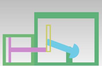
The mechanism used in this example is a Double-Slider Rocker Mechanism. It consists of three links (the Piston & the Crosshead is considered a single link) with one being designated as frame (or ground). It is connected by 1 slider joint, 1 pin joint & 1 roll-slide joint.
As designated in the figure, there are three links link 1, link 2 and link 3. Link 1 is the piston which is connected to Link 2, the follower, through a crosshead. Link 4 (the entire enclosure) is the ground.
The following table summarizes the joints.
|
Joint
Number |
Formed
between links |
Joint
type |
|
1 |
Link 1 and Link 3 |
Slider |
|
2 |
Link 1 and Link 2 |
Roll-Slide |
|
3 |
Link 2 and Link 3 |
Revolute
(or Pin) |
![]()
n = total number of links in a mechanism
![]() = total number of primary joints
(pins or sliders)
= total number of primary joints
(pins or sliders)
![]() = total number of higher-order
joints (cams or gears)
= total number of higher-order
joints (cams or gears)
we have,
F = 3(3-1) – 2(2) – 1
= 6 – 4 - 1
= 1.
Hence, the Valve Actuator mechanism has 1 DOF. In other words, this mechanism is constrained or fully operated with one driver.
Click here to get the compressed (Solid Edge) part files.