Dynamic Analysis
Step1
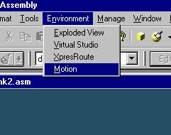
Start Dynamic Designer
Click Motion on the pull-down menu.
Step 2
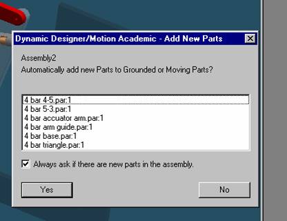
Add New part
Set automatically add new parts to grounded or moving part.
Click on Yes button.
Step 3
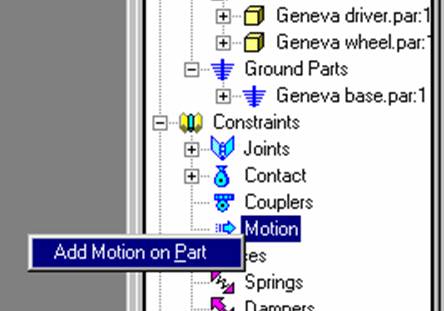
Add Motion to actuator arm
Right click on motion and select Add Motion on Part.
Step 4
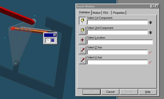
Select actuator arm
Select actuator arm as the first component.
Step 5
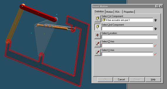
Select 4 bar base
Select 4 bar base as the second component.
Step 6
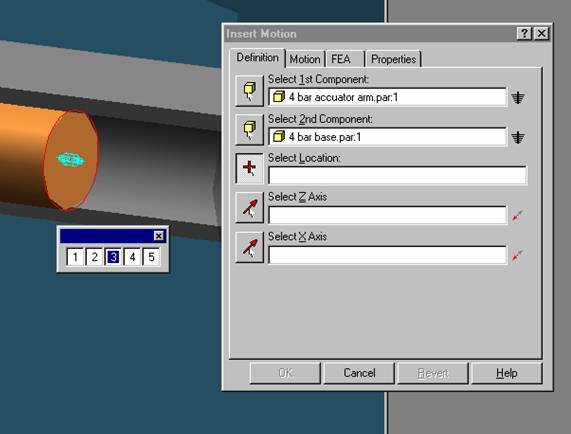
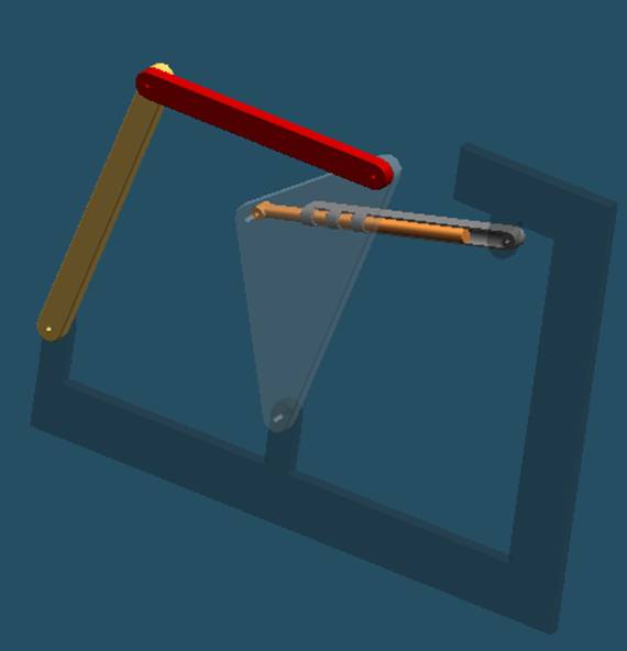
Select location of motion
Select the base of the long protrusion of the actuator arm as shown in the diagram above
Step 7

Select Z axis
Select a circle aligned with the long protrusion of actuator arm for the Z-axis.
Step 8

Select X axis
Select one of 4 bar base’s long horizontal edges for the X-axis.
Step 9
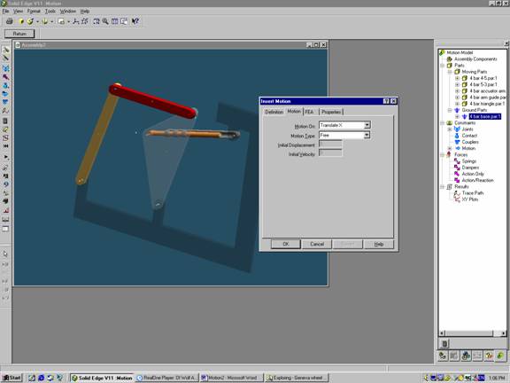
Select the kind of motion
Select the motion tab in the Insert Motion sub window.
Step 10
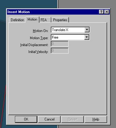
Leave motion as translate x
Leave the Motion On option alone.